Full Bridge Mosfet Driver
I have a full bridge MOSFET driver driver driving a full bridge. After some experimenting with the circuit prototype i found out that the driver heats up to over 60 °C after a short while of running, which concerned me but it worked fine. However as I decreased impedance across the load (which was originally connected to primary coil of a transformer) the driver started acting in a weird way and i found out that it has blown out. Bernard tschumi questions of space pdf download. This is already the second driver i destroyed this way and they're expensive as hell, so I need a solution. I think what's causing the driver to blow out is that when I decrease impedance across the load I basically create a short circuit between the driver's bootstrap pin and ground, which kills it. By adding a resistor across the load or the whole bridge and ground, I could easily solve the issue, however I do need low impedance on the load because I need high current (up to 20A). I thought about adding a resistor across the driver's bootstrap line, but I have concerns about it affecting the bootstrapping functionality.
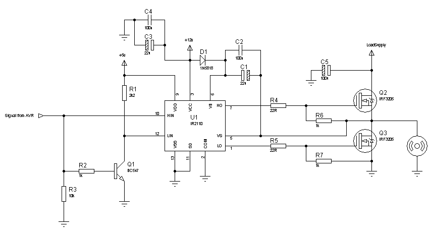
EDIT: I'm actually using IGBTs in place of MOSFETs (specifically IRGPS4067DPBF) Also I'm not posting a layout because the full bridge is not on a PCB but it's simply bridge-soldered to the driver circuit. The full bridge operates at 150 kHz square wave.Both circuit and load voltage is 12v Also here's my circuit schematic: The full bridge is connected as in the driver's datasheet, except the feedback loop and shunt resistor: Here's the control circuit layout: And here's the picture of the bridge. $ begingroup $ Show us a picture, please. There was a recent case (maybe 2-3 weeks ago) of a guy blowing his bridge driver. So I told him to put decoupling caps on the power rail and that solved it. Fast switching of a high current combined with supply wire inductance to create a nasty L*di/dt spike which blew the chips.
It wasn't load inductance in this case, simply the power supply wires. The nastiness (di/dt) is proportional to the current, so I'm not surprised it works at low current then blows when current gets high. $ endgroup $ – May 18 '17 at 16:38 •. Your layout may be sloppy. Blowing the driver out at high load current (as opposed to shoot through, which is independent of current) usually indicates that you have stray inductance which is causing excursions at the driver output that are unacceptable. Try adding some reasonable series gate resistance (15 or 20 ohms) and clean up your layout to minimize loop areas that carry load current.

Make sure you have bypass capacitors on the 80V and 12V buses. Generally 150kHz is quite a high switching frequency for IGBTs, also IGBTs are not a very good choice at low voltage- they have a lot of voltage drop.
LM5045 Full-Bridge PWM Controller With Integrated MOSFET Drivers 1 Features 3 Description. O High Side Output Driver MOSFET of the bridge with 1.5-A peak source and 2-A peak HO2 17 13 sink current. HS1 27 23 Common connection of the high side FET source, low side I Switch Node.
MOSFETs are typically a superior solution when voltages are low- their big advantage is that they are available and are inexpensive (small die size) with very high voltage ratings (eg. 1200V) and the voltage drop does not get worse.